Sonntag, 18. Juli 2021

yet another redesign

 Hi there,


I've changed the design yet again. I reworked the Z-Axis and Printbed and also added some weights (those big red boxes) at the bottom, to shift the center of mass. Right now the printer is very top heavy, which makes it shake quite a bit at higher accelerations. 

The parts are already purchased, shipped and partially assembled. I'll post a detailed description once everything is assembled and running smoothly.

klick to enlarge


cheers,

JHL

Freitag, 13. November 2020

Quick sneak peak

 Hey there, 


I haven't been posting for a while. Yeah, four years. It's a long time, but hey what can you do. My private life changed a lot so I had other things on my mind and honestly forgot about my blog for while. 

But I've been working on my design and now I want to share a quick sneak peak. I'll post a more detailed description of my work later on. Just give me few weeks.

Anyway, here is my current desing of my 3D printer as it is now (in CAD):


I haven't yet bothered with modeling the belts and dragchains, because they dont add any more valueable information to the cad file, but I will for showcase purposes later on. The buildplate and X-axis arent yet assembled, because I currently lack the funds to do them both. Thats why I'm concentrating on the X-axis first.

If you want to know more, check back in a few weeks for the detailed report.


until then, 

have a great rest of the week :)

Donnerstag, 22. Dezember 2016

Improvements and printed objects

Mornin’ fellas!


In the last weeks I worked on my printer and made some improvements.
I printed a deer had for my grandpas birthday. It came out pretty good, all the details were nicely printed and the support material broke of easily, but I still had the problem of vertical waves due to layer shift.


not the best example but somewhat visible

The cause for this was that I had the printbed only sitting on 3 M8 threaded rods and a 8mm smooth rod on the four corners. The 8mm smooth rod wasn’t stiff enough to compensate the circling motion of the printed which was induced by the production tolerances in the threaded rods. therefore the vertical waves had the same pitch as my threaded rods.

I decided to fix this and bought 12mm smooth rods(they bend not a single fraction of a mm under force ;) ) and LMF-12-LUU bearings. 


Some cutouts were needed on the printbed and because I didn’t wanted to measure out all of it and draw it on, I made a 2d drawing of it in Fusion360, printed it 1:1 on paper and simply glued that on with superglue.  


Luckily I didn’t had to drill and file it to dimensions, because I have a very handy tool for my dremel(or better: the „replacement dremel-tool“ because the original Dremel only runs on full speed… 0 or 1… I have no idea why, maybe I should open it and  search for the cause). 

I really like this craving-bit, it eats away aluminium like a hot knife does warm butter.
After I had finished the cutouts, I screwed in the bearings and printed some suited clamps to hold the rods in place.


The result of my little modification was really pleasing. The waves disappeared completely and the accuracy went from +/- 0.5mm wall thickness to ~0.1mm. The fourth corner is still only hanging on a bearing and a 8mm smooth rod. I don’t quite like this, so I think I’m going to put in a 4. Z axis motor with a threaded rod for this corner to improve accuracy.

But for now my prints look really good. The surface is still not perfect though. I think I can blame  the filament quality up to some degree on this, because I bought a really cheap one. Furthermore I like to print at pretty fast speeds. Partially the fourth corner is also to blame as I said.

These are the things I printed with my improved printer:


This is a mug-holder which can be attached to the ventilation slits in a car. Here you can download it, I designed it: http://www.thingiverse.com/thing:1988960


fun fact: no support used...


Cheers,
JHL

Dienstag, 20. September 2016

Casing and Rebuild

Hello at all!


So my summer holidays ended 3 weeks ago and because I have my A levels this year I was pretty tied up in school. I'm also learning how to drive at two days of the week in the afternoon. As you can guess there is not much time to work seriously on a 3d printer. But on the weekends I took my time and finished reprinting my entire plastic parts. They were originally printed on my first printer, which had, let's be gentle, a quite medium quality finish. On top of that the X and Y axis were shifted at nearly a degree.

Yeah, I was happy with those parts....


...as long as I saw what my new printer was capable of and then decided to rework the whole design.


###
About the new design:

I'm thinking about making it open source, so everyone can build one themselves in their own shop or something like that. Open source is awesome, I really like the way of sharing work for free.
On the other hand I considered making it open source, but only with a private use. I don't know yet. But what I know is that you will be able to download the files and use them for your own projects.

When the 3d printing stuff on my 3d printer is working fine I'm planning to continue in the same way.   I'm planning to make a interchangeable toolhead for not only 3d printing gear but also for pcb-milling, small laser diodes and pick and place/solderpaste dispensing. Since the motion system is already there with everything to make it run, I only have to tweak a few things, mod the marlin firmware and have a tiny all-round prototyping factory in my bedroom :) (Yeah kind of like the >>fire pick delta<< from hackaday but as a corexy. I don't want to make a clone. I just came up with this thought when my printer was running and I thought about how awesome it would be if everything else from my projects can as easily be made as my mechanical parts)
###


 I made it more easy to assemble and better in terms of stability and accessibility. I began printing in my last week of summer holidays, printed one to two parts per day and continued it on the weekends when school had started.


 Now I'm finally done and can begin assembling it.
This is what it looks like now(the screws are of course not printed):


To give you a idea about speed: every piece took 14h (2 x 7h)


Casing


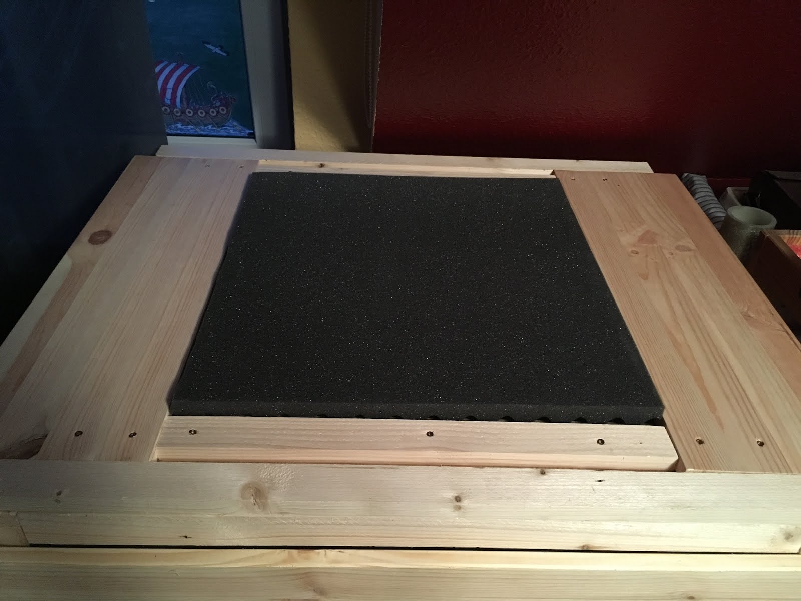
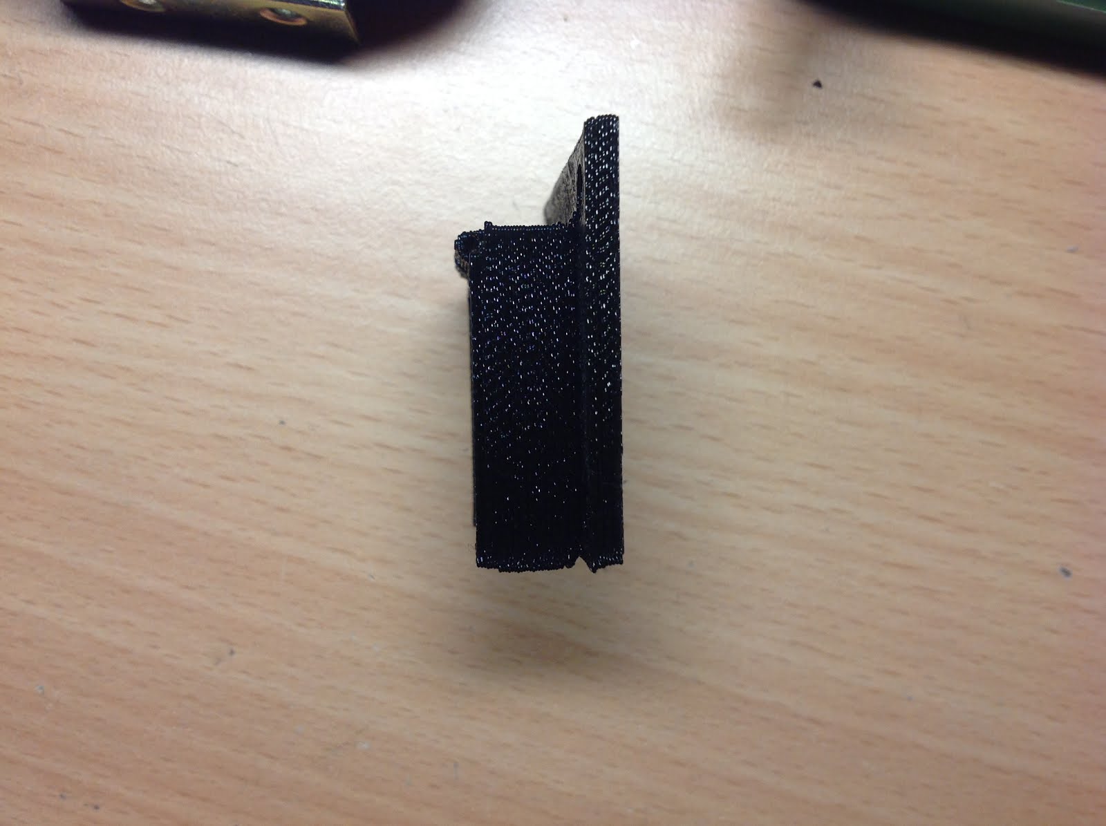
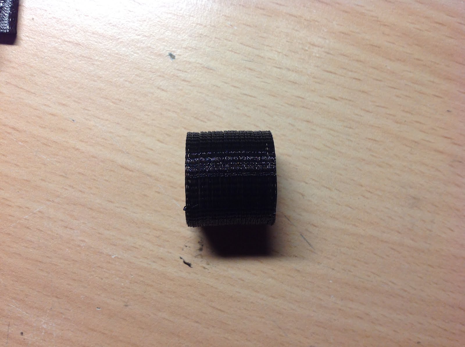
Because of the quite noisy sounds a 3d printer, or better MY 3d printer, makes, I decided to build a wooden casing with sound-filtering foam an ventilation. My aim was to make the whole thing so quiet that I could let it run over night and be sleeping in the same room. 
Of course I couldn't make that work. As always when I think about things to build, I'm way to optimistic and euphoric. I would compare myself to an eight-year-old at christmas. I only see how awesome things could be and mostly repress the difficulties I have to face. 
Yes, the casing is made out of wood and ventilated. 
Yes, it cancels out the sound, but only some of it. It is so quiet that, if I'm in the same room and have music playing, I hardly notice it printing. But over night this is far too noisy to sleep next to.


The front and back panels are detachable and the top has a little plexiglass window in it with optional sound foam.


While making those my room kinda looked like I was building an professional recording studio ;)


Furthermore: I hooked up a spare raspberry pi I had around with octoprint. It works like a charm, I can access my printer from anywhere on the network with any device  an check my print. It is super easy and a great help for me.


Thanks for reading!

Cheers,
JHL


Montag, 8. August 2016

New Things *.*

Hello there! Do you guys still know me?


I know, I've been very quiet after my last post, which was back in the December last year... Long time, I know. But there is a reason for that. It's because:

I've build a new printer!

Bigger!

Faster!

Self designed!

More accurate!

Better looking (not yet fully, but way better than the other :b)!

This is the bad boy
It is based on the CoreXY movement system.
Why?
Because I think it is way more advanced, due to the special arrangement. None of the motors is tied to an axis, which makes the moving parts lighter. That again gives me the ability to move the axis faster.

I also decided to go for a Bowden Extruder with this one, because it, again, reduces the weight which has to be pushed around, and gives better results in print quality.

Furthermore I gave up the wish to make my own electronics and software. It sounds sad I know :(
But if you take a closer look it makes sense:
- developing a driver board on my own has the downside that it costs a lot. I'm obviously working with a tiny budget (which is my pocket money) and there were a lot of problems and difficulties because of that. In the end it wasn't fun anymore.
- writing the software on my own is neat, because I know the inner mechanics and I'm able to implement my own functions easily without the time I have to spend now to read the marlin documentation. I really liked that. But I was very unexperienced when I started: I didn't knew about the inability of the raspberry pi to do precise realtime things, Interrupts where a horror to implement(in contrast to arduino) and the code was evolving with my skills. Which means that there were snippets which were really awfully coded and messed up. All of this lead me to a point where I lost the fun I had doing this. In the end, I procrastinated the things I wanted to change on the code.

That should be enough for the topic "reasons why I gave up".


Back to my new printer:
- RAMPS 1.4
    - with a self-made breakout board to power 3 Z axis steppers
- Marlin 1.6.7
- print volume: 300mmx300mmx530mm
- auto-bed-leveling
- (until now without a heated bed  -  PLA works fine on blue painters tape)

Here are some pictures of my most recent test print:

- 0.2mm layer height, 2½ h, PLA, 185C°, 6,5cmx3.2cmx4.9cm
The Z axis is, apparently, a bit wobbly, thats why there is a vertical wave pattern on the print.
In the next days I'm going to get some more precise M8 rods.


So that was a tiny update on what was going on in the past 7 months. I'm sorry that I didn't made the video I announced in my last post, but my other Printer is no longer in a presentable form. I had to re-use the steppers and the extruder, because, as I already mentioned, I only have my pocket money for this project.
Obviously there won't be a video about this printer in the future. But maybe about my new printer. I don't know for sure yet.

I think I will post some more about this printer in the future... if I'm in the right mood for writing ;).

Cheers,
JHL


Montag, 28. Dezember 2015

Hello to y’all out there!

Today I printed my first pieces*!


* I printed a lot of calibration pieces while working on it, but the don’t count as real pieces, I guess..


The first two are pieces of a safety cap for my power bar which powers my printer. Until now the main switch was uncovered and could easily be pressed by accident, shutting down the whole printer and ruining the print.

They came out, I would say, well, considering the fact that this is a printer made out of scrap wood and build while I had no idea how to do it right :) (This whole project is more of a learning by doing kind’a thing)
They might be looking awful on the pictures, but in real, they look well. And this isn't the finished state, I'm still working on it.


Some different angles of the power safety cap:


After printing the safety cap, I printed a cylinder with no top and bottom layers, no infill and only one shell. I really have to confess, that I thought this wouldn't come out as good as it is now. There you can see, that my printer is quite accurate. Each layer is on top of another, nearly no shift.


That's it for now. I will make a video about my printer, but only in a few weeks time.

Cheers,
JHL

Freitag, 4. Dezember 2015

Almost Done!

Hi Folks,

I honestly thought that I would post more and especially some vids about my printer. But, yeah, I was lazy and the whole thing ran not like I expected it to. (As you might have guessed, I'm pretty inconsistent with my online presence)
I build a heated bed out of strip-board, re-engineered the whole X-axis-slider and Z-axis (now out of aluminium), bolted it all down to my table, to reduce vibrations and wrote some code for the firmware.
Long story short: I got it to run as I wanted it to, so I'll post a video about that soon.
For now, I'm gonna leave you with this picture of the current state of my Printer.


Cheers,
JHL